top of page
section
PD
SECTION 6: Technical understanding (DE)
Before starting this section (the most technical of them all in terms of a mathematical and physics approach), you should have some previous understanding of:
-
Structural integrity
-
material finishes
-
products and system movement
-
electronic functionality
-
modern, smart and composite materials
-
fabric reinforcement
-
standardised component use
-
surface finish treatments/ processes
6.1 what consideration need to be made about the structural integrity of a design solution?
Topic pre reading - what should you already know?
Click here
you buy something. it breaks... your would be a dis-satisfied customer and potentially not but from the same company again, especially if you were injured as a result of the fault. Here we look at what makes products function and function well.
A good product:
makes good use of material
is resilient
has structural integrity
has functionality
is aesthetically good
structural integrity
the ability to withstand forces and applied pressure
apply force here and the table is fine
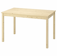
apply force here and the table leg may break
sitting like this is fine


sitting like this will snap the leg
the question is, have the full range of forces been considered when designing?
structural integrity isn't always physical (like the examples above), it can also be electrical or material.
For example:
if you put a battery in an electronic device the wrong way round it may cause failure or damage (fault, fire, etc.)
If you use an unsuitable material which is not able to withstand the environment it has been put in - consider the weather/ temperature/ uv etc.
Enhancing structural integrity
So, as you have seen so far, it's incredibly important to ensure a product doesn't fail in terms of collapse or damage. on some occasions its necessary to give a little more to ensure a product survives. We can do this through:
Material reinforcement - enhancing the design of a part or component which is likely to be subjected to lots of wear. For example, adding additional protectors to the corners of a suitcase.
Material Stiffening - This is where you increase the strength of a part by adding webbing or ribs to the hollow of a shell structure. For example, the underside of a 'wheely chair'
Material protection - This is where you apply a protective finish to a material to prolong its durability. Examples of this include paint, varnish, galvanizing and anodizing.
Triangulation - structurally, certain shapes are stronger or weaker than others. A common weakness is found in square or rectangular frames. Strength and rigidity can be improved through the use of triangulation. See below:
If you push here...
This will happen...
Unless you use triangulation
So far, all that has been considered is that of static products (ones that might not need to move), the rest of section 6 is about the application of movement in order to make products function mechanically.
6.2 how do mechanisms provide functionality to products and systems?
The basic machine principle
A mechanism is a system designed to control forces and motion in a product.
A well designed mechanism will trade force (input), for movement (output).
generally speaking a mechanism will either reduce speed but increase force, or the opposite, increase speed but reduce force.
(input force x input speed) = (output force x output speed)
(input force x distance moved by input) = (output force x distance moved by output)
or if no speed is involved/ focussing on movement
working this out is called mechanical advantage and depending on what info you have available, is done so like this:
MA = output force
input force
MA = distance moved by effort
distance moved by load
MA = input arm length
output arm length
MA = load
effort
Similar to MA, in terms of working things out, the calculation for working out efficiency is:
Efficiency = output power
input power
In an fully efficient mechanism, no (or very little) energy is lost through friction, heat or sound. Though this is rarely the case meaning that the output power/ torque will usually be less than the input power/ torque. This can be calculated:
x 100 = ......%
Actual mechanical advantage
= measured output force
input force
Efficiency = Actual MA
ideal MA
efficiency in mechanical systems
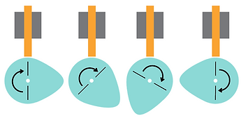
types of motion:
for any mechanical product (a product that includes a mechanism), movement/ motion is key and can occur in 4 different ways.
linear
in a line
rotary
round and round
reciprocating
back and forth
oscillating
swinging
Changing magnitude and direction of forces and torques:
that's a mouthful... but basically it's referring to the fact that force (see below) and motion is pointless unless you can do something with it - making something function. And this is how you achieve it:
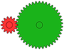
Gears
Used as a method of converting/ transferring rotary motion, in some examples to slow it down, in others to speed it up.
The calculation for working out Gear ratio is:
number of teeth on the driven gear
number of teeth on the driver gear
.png)
in this single gear train the calculation is
driven = 42 = 3
driver 14 1
this gives a gear ration of 3:1 - the driver must rotate 3 times to make the driven rotate once
Other things you should be aware of when exploring gears (spur gears in this case):
RPM - revolutions per minute - how quickly a gear rotates
PCD - pitch circle diameter - the diameter of a gear from half way down the tooth - this is used to work out how far gear shafts need to be apart from each other
Module - This is used to work out the tooth pitch (how many mm each tooth takes up around the circumference of the gear)
torque - how much force is required to cause a rotation
torque = force x distance
Working out module:
module = pitch circle diameter (mm)
number of teeth

PCD
the modules on connecting gears must be the same in order to mesh properly
If you join multiple gear trains together you create a compound gear train
A
B
C
D
A 120 teeth
B 40 teeth
C 80 teeth
D 20 teeth
driven (B) = 40 x 1
driver (A) 120 3
driven (D) = 20 x 1
driver (C) 80 4
1 x 1 = 1 = 1:12
3 x 4 12
12
Other gear types
The examples above look at general spur gears. For alternative applications, other types of gear are required and include the following:
Bevel Gears

Usually at 90 degrees, bevel gears transfer rotation across 2 axles and can be used to increase/ decrease ratios

Mitre gears
Similar to bevel gears but these will be the same size, only transferring direction, not changing ratios.
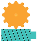
Rack & Pinion

Used For changing from rotary to linear motion
Helical gears

Unlike a spur gear the teeth are on an angle. This allows the teeth to meet more gradually creating a smother connection
Spur gear
Helical gear
Worm drives
A worm gear is used to create high gear ratios and transfer the direction of rotation. E.G. Rotating on different axis can enable the worm to rotate 60 times to turn the spur gear just once (60:1). This is a high friction set up but alongside the high ratio there is not backward motion (the worm can only rotate the gear - it will not work the other way round.
epicycle gear systems
These complex gearing systems can provide a variety of gear ratios depending on which axle is used as an input/ output.

Unlike spur gears which run on axles side by side, epicyclic gear axles can be on a direct line

Sun axle
Ring axle
Planet pinions
levers (single)
A simple mechanism with an input, fulcrum and output designed to turn one movement into another or increase/ decrease mechanical advantage. There are 3 classes which can either increase or decrease input/ output.
E
Class 1
L
Example: crowbar or scissors
E
Class 2
L
Example: Wheelbarrow or Nutcrackers
E
Class 3
L
Example: Tweezers or human arm
E = effort - the input
L = Load - the Output
= Fulcrum - the point of movement - this can be fixed or floating
Working out mechanical advantage for a lever:
the main point of using levers in to increase or decrease input/ output. Working this out is known as working out the mechanical advantage and is done like this:
MA = input arm length
output arm length
MA = load
effort
MA = distance moved by effort
distance load moved
100N
L
600mm
200mm
MA = input arm length
output arm length
MA =600 = 3
200
The input effort of 100N is increased to an output effort of 300N
In this example we know the input/ output arm lengths and the input effort
levers (compound)
Simple lever types such as the examples above are great for producing simple movements and lower levels of mechanical advantage. On occasions, much more complex movements and larger levels of mechanical advantage are required and to achieve this a compound lever is required - This is where 2 or more levers are joined together. Examples such as tweezers & bolt cutters are examples of this.
E
E
A
800mm
200mm
L
B
600mm
200mm
L
*depending on the position of the fulcrum the output can be increased/ decreased.
To work out the mechanical advantage with a compound lever you need to break the lever down into sections, each with their own input, fulcrum and output. For the example in the box above there are 2 levers (A & B) and you would do the following calculation:
Compound (overall) MA = (MA of lever A) x (MA lever B)
MA lever A =600 = 3
200
MA lever B =800 = 4
200
3 x 4 = 12
Linkages
these are collections of levers and other devices used to change motion types/ directions and include examples such as a crank and slider, a peg and slot or a bell crank.
Working out mechanical advantage with linkages becomes more complicated as you have to consider angles within the movement - this is where your A level Maths & physics comes into play.
MORE TO COME
Crank & Slider
Rotary motion
Reciprocating
motion
INput
Fixed pivot
Bell Crank
OUTput
INput
Fixed pivot
Floating pivot
Floating pivot
pulleys & belts / Sprockets and chains
Used for transferring rotational motion across further distances, both pulleys/ belts and sockets/ chains will also allow you to keep your direction of rotation the same. Obvious example of where these are used are on bikes, transferring pedal power into back wheel movement.
Both systems allow for an increase or decrease of ratio depending on which way round the gears/ wheels are used.
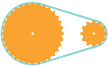
gear ratio = teeth on output
teeth on input
With chains and sprockets it is key that they match in terms of module and link distance on the chain - this will ensure they mesh properly.
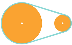
gear ratio = output diameter
input diameter
Quieter that chains and sprockets and often used in applications where lower loads and levels of torque are applied, belts and pulleys are still widely used. There are a number of belt types available, including V-belt, Toothed and flat belt. All belts must be used at an appropriate tension to prevent slipping or excessive friction.
axle
V-belt
Screw threads
Another method for converting rotary motion into linear motion - imagine a nut moving along a bolt then it's undone.
If a bolt has a thread pitch of 2mm, it would take 5 rotations to move 10mm. Easy math.
Cams and followers
This mechanism is used to convert rotary motion into linear motion and consists of 2 parts. Some examples of the setup can be seen below:
Pear cam
flat follower
For half of the cams rotation there is a steady rise and fall of the follower, for the other half, no movement. A flat follower causes friction and an inaccurate follow of the cam
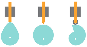
Snail cam
Roller follower
A continuous rise and the a sudden drop. The roller follower provides a smooth flow of the follower. (this type of cam will only work in one direction (clockwise here))
Eccentric cam
knife follower
A continuous rise and fall provided by the cam - a very accurate reaction from the follower
Working it out
There are 3 thinks to observe with a cam:
> stroke: this is the maximum distance the follower can rise
> rise interval: this is the number of degrees the cam rotates to produce the full stroke
> dwell: this is the number of degrees the cam rotates without causing follower movement
dWELL
EVEN THOUGH IN THE EXAMPLE ABOVE THE CAM HAS ROTATED 180 DEGREES, BECAUSE THE DISTANCE BETwEEN THE CENTRE AXIS AND BASE OF THE FOLLOWer HAS NOT CHANGED, THE FOLLOWER HAS NOT MOVED. If the cam continues to rotate, the follower will begin to move.

Stroke rise interval
In this example the follower only raises (stroke) by the same distance between the cAm at its dwell stage and its highest point. in this example it is shown in red and only takes 90 (A to A) degree rotation to produce it (rise interval)

A
A
bearings and lubrication
Friction is something which can contribute to the effective movement of a product component, a wheel spinning, or axle turning for example. To provide a frictionless (or significantly reduced) rotation in these parts, bearings and lubrication can be used. Depending on the mechanism and direction of load being applied there are a couple of factors which must be considered.
How long is the axle/ shaft - it may be long and need a number of supports
there may be axial load - force is applied along the axle or shaft
There may be radial load - force is applied sideways/ down
Axial load
Radial load
Shaft/ axle
Bearings
Wheel
Nut
Longer axles/ shafts may need to be supported in more than one place to ensure they don't bend and cause gears to slip.
bearing types
Simple bearings can consist of a basic polymer (nylon/ PTFE) collar which acts as a barrier between the two rotating parts. With lubrication (grease/ oil/ graphene) it can reduce friction. A self lubricating material such as brass could also be used but this will wear away over time and need replacing. If a more substantial bearing is required you can consider the use of one of the following types:
Ball bearing & Sealed bearing
Very similar in construction, metal balls are housed between 2 races. the main difference being that on a sealed bearing you can not see/ access the balls. Both lubricated with grease, the regular ball bearing can be prone to debris contamination.
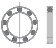

Sectional drawings of a ball bearing (left), and a sealed bearing (right)
Tapered bearing
A tapered bearing uses tapered rollers and not balls to rotate its races. because of this it has an added resistance to axial load as well as radial load.

Fluid bearings
For a further increase in efficiency and longevity, fluid bearings can be used. They offer better resistance to load in high performance and high speed operations. Take a game of air hockey as an example of how friction is reduced by the introduction of air.
6.3 what forces need consideration to ensure structural and mechanical efficiency?
A structure is something which is designed to either hold its own weight of the weight of something else. This can be in terms or either:
Static force
This is a stationary force and does not change. E.g. a parked car on a manhole cover.
This is relatively straight forward to work out as its based on the mass of the object.
Can you think of an example?
OR
Dynamic Force
This is a moving force and may change position or size. e.g. a demolition ball being used to demolish a building.
This is more difficult to work out as the applied force can not always be calculated. When this is the case, engineers use a safety factor of 2, 4, etc depending on the application/ danger.
Can you think of an example?
Key things to know:
Force is measured in Newton (N)
Mass (the amount of material an object contains) is measured in Kilograms (kg)
Weight (force of gravity pulling an object) is measured in Newtons (N)
MASs vs Weight
Commonly mixed up - weight is a force, not the ... weight!
If you weigh something at the shop, it should actually be in newtons.
For any calculations you might need to do, you need to consider that to work out weight you need to know the following:
weight = mass (kg) x gravitational field strength
(on earth, gravitational field strength is 9.8n per kg, on the moon it's only 1.6 n/kg
Types of force
When forces are applied to materials or objects it can make them change in shape (squashing, stretching, bending, twisting). Depending on what the material is and what form it is in will determine how it might behave. consider the following cross sections when looking at the forces below - which would resist each force the best? What if the profiles were longer or shorter? Don't forget other characteristics which might still need to be considered such as weight, cost, malleability or methods of joining.
tension
forces pulling in an opposite direction - the material is being stretched. Remember Youngs modulus here.
Compression
forces pushing together - the material is being squashed.
Shear force
forces pushing in opposite directions - against each other to create a cutting like action.
Torsion
This is rotational force applied in a twisting manner - the bigger the torque, the more force is applied.
Bending force
Not technically a type of force but an object will often react in this way if a force is applied along it's centre. It causes compression on the top and tension on the bottom, sometimes causing the top to bulge and the bottom to split/ tear.

As mentioned already, when the forces above are applied to objects, they can change in shape. Part of An engineers job is to work out how much of a particular force an object can take. This is known as working out stress and strain, which in turn is used for calculating Young's Modulus:
Stress
A material, once a force is applied and depending on it's particular form will have a stress and it can be worked out by:
Stress = force
cross sectional area
Stress is measured in pascals (pa) and 1 pa is equal to 1n/m
-2
Strain
The stress a material is subjected to will cause it strain (to stretch). This can be calculated by:
Strain = extension
original length
Strain isn't measure in units as it's calculation is a ratio of lengths.
When we know the stress and strain of a particular material, you can work out its Young's Modulus. This is the stiffness of a material (the stiffer a material is, the less elastic it is).
Young's Modulus = Stress
Strain
Young's modulus units are PAscals (pa)
It's important to know/ be able to work out the Young's modulus of a material when selecting materials for their ability to hold a weight.
Consider the material use as changes in temperature etc may effect the YM of a material.
6.4 how can electronic systems offer functionality to design solutions?
A design engineering project (and possibly product design ones too), will include the use of electronics. An application of your understanding of the below content is what you will be assessed on and what will make for a good project. Obviously you will be assessed on your understanding through the exams too.
Like all other topics, think about what you already know. What can you remember from GCSE physics or DT?
You should remember the following:
Voltage is the difference in charge between two points. Measured in Volts
Current is the rate at which charge is flowing. Measured in Amps/ milliamps (ma).
What do you remember?
Ohms law
Voltage = current x resistance
(volts)
(Amps)
(OHMS)
V = IR
Power = current x voltage
(volts)
(Amps)
(watts)
P = IV
When working with resistors (see below) the following formula can be used:
P = Power
V = Volts
R = Resistance
I = Current
P = V
R
2
or
p = i r
2
In short, electronics works as follows:
Input
Control
Output
Electronics can become incredibly complex and for design engineering students you will need to explore it in some depth. First, lets start with some basics.
Quite often, it will also need to include a selection of passive components - components that do not amplify or control signals, just current.
Passive components:
Resistors - these components control the current that is able to flow around a circuit. The main reason for the use of these is to protect delicate components against too much current. Too much power to the resistor can cause it to 'blow', so working out it's rating is important.
You can work out the resistance of a resistor based on its band colours.
Example:
470Ω 0.25w resistor, 12v power supply
P = V = 12
R 470
2
= 0.3w
2
So if you note that the resistors power rating is 0.25w and that it needs to be a minimum of 0.3w. We need a resistor with a larger capacity for this example, say 0.5w
symbol for a Resistor
Capacitors - These components store electrical charge
Smaller capacitors are usually made from ceramic or polyester and are not polarised (electrolytic). this means they can go either way round in a circuit (no + or -). Larger capacitors are polarised and will only work a particular way round (+ first).
Capacitance is measured in farads/ nano-farads/ micro-farads
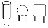
Capacitors can take various forms but usually look like one of these. two legs, the shorter identifying the - and the longer identifying the +
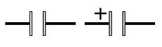
symbol for a Capacitor and a polarised capacitor
Diodes - these are polarised (one way) components and only allow current to flow in one direction. They consist of an anode (A) and a cathode (K) - current can only flow from anode (+) to cathode (-)
Diodes can be used to prevent current flowing the wrong way round a circuit if a battery is put in the wrong way.
Diodes will prevent current flowing to multiple components unless in an and/or situation (see below).
Diodes prevent EMF (electrical spikes) when an electrical motor or solenoid is used in a circuit.

symbol for a diode

In this example the current can only flow to red and blue when switch A is closed. Because of the diode, when switch B is closed, only blue will illuminate.
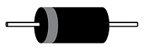
a diode
Power supplies for electronic systems
This might sound blatantly obvious, but for an electronic circuit to work it mush have a power supply. It's the first thing to check if a circuit isn't working.
Non - renewable examples:
> batteries (Zinc-chloride/ Alkeline)
> power supply unit (PSU)
These are much more reliable as sources of power but consideration of the appropriate type needs to be considered, (depending on your outputs and current requirements) when designing circuits.
renewable examples:
> solar (with rechargeable batteries)
> wind generator (with rechargeable batteries)
Rechargeable batteries:
Nickle-metal hydride (nimh)
lithium polymer
lead-acid
If you use batteries, how do you:
charge them?
remove them?
Options...
> batteries
When focussing on your project, Even if you design and develop with a PSU and move to batteries later, you need to consider the power they will provide. This is known as battery capacity (milliamp-hour (mah)) and is calculated in the following way
Capacity (mah) = current (ma) x time (h)
time (h) = capacity (mah)
current (ma)
Example:
You have a torch and it pulls an average of 25 ma from a 600 mah battery, this would be the calculation, providing you with a guide for how long it would last.
time (h) = 600 (mah) = 24hrs
25 (ma)
Inputs
So you have your power supply... now you need a method of 'inputting' a signal. This is known as an input and can come in a few different forms:
Physical switches
These are used to complete a circuit and can be in a switch or button form. Examples include an i/o microswitch, a press to make button or a press to break button and require a physical movement to activate them.
There are switches which act more like sensors and don't require physical activation like the above examples. They can be activated by a movement in their proximity. Examples include:
> Magnetic Reed switch
> Magnetic Hall effect sensor
> Opto-switch (reflective and slotted)
> Rangefinder distance sensors (ultrasonic and infra-red) (up to 1m activation)
> Quadrature rotary sensor (creates a pulse on each 'clicked' turn
Each of the sensors above can be used in a variety of different ways and for different purposes, to gauge speed, rotation and distance are just a few examples. How you create the system that that will input these will be part of your problem solving.
Force sensitive resistor
Used when the application of force is used to 'switch' something on. As a load increases, resistance decreases allowing current to flow.
Load Cell
A more accurate and complex version of a FSR, an amplifier is used to amplify the resistance to gain a more accurate reading to provide a signal (for a microcontroller)
To view further details of all sensor types, click here.
All of the sensors detailed above have been around for some time, however With more recent technological development, there has been more development in technology, in this case, sensors. They have become smaller, more accurate, quicker and more advanced, allowing for the development of many products, including a variety of electronic products from mobile phones and cars to central heating and microwaves.
In terms of prototype development for your NEA, this causes a few issues - many of the components (sensors included) are too small to work with. Because this is so, many manufacturers have incorporated them into breakout boards to enable developers to work with them.
An example of a breakout board similar to the ones we use in college can be found here

Whereas a traditional electronic circuit may have just included an input and an output, since the development of the microchip in 1958 by Jack Kilby, electronics has progressed massively. Acting like the brains of the circuit, a microchip will process inputs in numerous ways, all dependant on the pre-programmed instructions it is stored with.
Microchips can interface signals in 4 different ways (INPUTS):
Digital Switch Sensor (input)
These are basically switches, either on or off (i/o). When they are off, no current can flow to the microchip so no signal is received. Once the switch is on, signal is received and an instruction can be processed.
When a digital switch is used with a microcontroller a pull down resistor is used to prevent too much current from damaging the microcontroller.
Analogue resistive sensors (input)
Used in a similar way to a switch, an 'ARS' can input a range of analogue input (not just on or off). Imagine a dimmer dial... Examples are an LDR (light dependent resistor or a thermistor.
Note that if using an analogue input you must use an analogue leg on the 'MC'
Analogue/ digital output sensor
Microcontrollers can read and store analogue/ digital outputs from sensors. These input readings are then accessed by the program and used to create further actions/ outputs. The sensor type must be considered and calibrated to give value to the value read.
Data stream output sensor
Similar to analogue/ digital output sensors, however instead of providing a voltage signal, these provide an alphanumeric reading. This makes the system more complicated and developers of microcontrollers usually provide software and libraries which allows for the information to be selected, processed and transferred into an instruction/ signal.
When considering the microchip you might use in a circuit, you need to consider how many different inputs and outputs you might require. There are various chips available ranging from 8 legs upwards. Each chip/ controller includes an +v leg and a 0V leg and then a selection of inputs and outputs. For example:
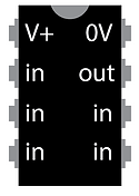
Both inputs and outputs can be either analogue or digital - digital meaning essentially its on or off, but analogue meaning a range or scale of input/ output can be achieved. This is particularly useful if you are wanting to achieve a range of outputs, e.g. varied speed, light level or sound.
Lets presume each of the inputs on this chip is analogue; Each of the analogue input legs on this chip has an analogue-to-digital converter (ADC) which converts the voltage 'read' by the leg into a number. This number is calculated in proportion to the overall circuit voltage.
Knowing this allows the user to work out how many levels can be read by the chip and in turn, how many numbers can be produced - this means they can look into the accuracy/ variation of, for example, lighting or speed.
Some examples:
An 8 bit ADC will produce 2 = 256 levels so the number range is 0-255
A 10 bit adc will produce 2 = 1024 levels so the number range is 0-1023
The full scale input voltage which is the voltage needed to create the upper level (either 256 or 1024 in the examples above) is usually the same as the power supply voltage. for example, if the circuit voltage was 6v then the Full scale input voltage would also be 6v.
8
10
To put some context to this, (on the above 8-bit chip) if a circuit supply is 6v but the input, (lets say because of an LDR use), is 4.2v then the following level would be the outcome, creating (based on programmed instruction) a particular output.
Input voltage
supply voltage
x full scale value
4.2v
6v
x 255 = 178
In the example above, it might be that the full range of 178 might not be required so the ACD can be scaled so the analogue input is only read between particular levels. this only creates an output for particular readings, for example, a light that comes on when its getting dark might only do so at a 50%-80% light light level, but the actual light is on between 0% (completely off) and 100% (as bright as it can go).
Much like the varied (Analogue) input, many microcontrollers can do the same with outputs, to, for example vary the brightness of an led or speed of a motor. It does do this slightly differently and rather than creating a level as with the inputs it will pulse a signal at the appropriate intervals, known as pulse width modulation. This pulse, rather than creating a constant reduced power output, creates bursts of full power output.
This needs reading through a few times...

Once the power has been hooked up, the input has been activated and the signal has been sent to the microcontroller, it can follow the instructions it has been programmed with and activate the appropriate outputs, which come in the form of...
Light
Light emitting diodes (LED's), available in a range of sizes and colours, including white and colour changing (combining red, green blue).
An LED is polarised and has a shorter leg to show you which is negative. It also has a slight flat on the negative side.
To calculate resistance required for LED's:
LED symbol
The arrows represent the light moving away
R = (V - V )/I
S
led
V S = power supply voltage
V LED = Voltage drop across the led
I = Current required for led illumination
both of these can be looked up
Sound
Microcontrollers can be used to create sounds from clicks to full songs and verbal audios. To convert electronic signals to sound waves a piezo-electric sounder in incorporated into the system. These can create loud sounds but for louder volumes an amplification device would be needed.
Speaker symbol
Movement
Creating movement is key in many engineered projects/ products and there are a number of ways to produce it.
Solenoids
Motors
Piezo actuators
M
Information
Most electronic products include some sort of display panel, some of which will be made up of LED's. They will be one of 2 types:

7 segment
The required LED segments are illuminated through the use of a microcontroller. Popular in clocks and ovens etc.

Dot matrix
Similar to 7 segment where specific segments can be illuminated, with dot matrix, specific LED's can be illuminated in sequence to create messages of text/ characters. if these characters are changed rapidly it is known as multiplexing, allowing longer messages to be displayed without having huge display panels and lots of wires. A dot matrix can either be LED or LCD.
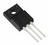
signal amplification
Sometimes it's necessary to amplify the current in a circuit, allowing for a larger current to provide enough power for more demanding components. An example of this can be seen in the use of a Mosfet.
Electronic circuits and mechanical
Networking and communication
-
wireless devices
-
embedded devices
-
smart objects
-
information exchange
The basic principles of electricity
-
voltage
-
current
-
Ohm's law
-
power
More content to come
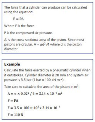
pneumatic components
More content to come

6.5 how can programmable devices and smart technologies provide functionality in system design?
Programmable devices
-
Enhanced features
-
measuring, controlling, storing data and displaying information
-
electronic prototyping platforms and integrated development environment(for simulation in virtual environments)
-
robotic arms and cars
-
flowcharts and process decisions
More content to come
Smart materials
-
colour changing
-
shape shifting
-
motion control
-
self cleaning
-
self healing
More content to come
Time to test your knowledge. Click on the link below and enter the room ncbdt6
Access exemplar exam questions for this section here
log into memrise and then click below
.png)
test your section 6 key terms understanding here
Design Technology @ NCB
bottom of page